Every die is balanced twice. Once on the drawing board and once at the press. The second one is the expensive one.
Aluminium does not flow evenly through a die on its own. A thick section drains the billet faster than a thin one, a wall close to the container edge sees less pressure than one at the centre, and a leg standing in the metal path shadows everything behind it. Left alone, the profile leaves the die with one end running ahead of the other and it bends, twists or tears on the run out table.
The bearing land is where a die designer answers all of that. It is the parallel surface at the die exit where the metal is held back by friction, and its length is the only knob that can be set differently at every point around the profile. Longer bearing, slower flow. Shorter bearing, faster flow. Getting the lengths right is what balancing a die actually means.
Bearings are not hard to understand. They are hard to build. On a hollow die the bearing surface follows the whole perimeter of the profile on the die plate and the whole perimeter of the mandrel, with transitions and height changes at every step. In a general purpose CAD system that geometry is drawn by hand, feature by feature, and it is redrawn from scratch whenever the bearing plan changes.
The bearing lengths on the mandrel and the die plate are the important factors affecting the flow of aluminium in the die set. In classical CAD systems it takes a long time to model them. ExtrusionPower, Bearing Wizard FAQ
That is also why the bearing plan tends to be the first thing that gets frozen and the last thing anyone wants to revisit. The information is usually already on the 2D drawing: the designer has written the transitions and heights there. What costs the day is carrying it into 3D. In ExtrusionPower the bearing definitions are read from the 2D drawing and applied to the 3D model automatically, which the catalogue describes as removing what is normally the most time consuming part of die modelling.
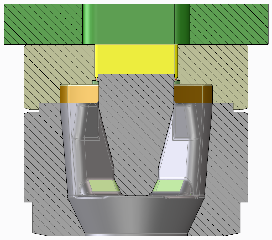
Once the die exists in 3D, there are three honest ways to decide what the bearings should be, and it is worth being clear about which one you are using.
The lengths come from the designer, from the shop standard and from experience with similar sections. This is how most dies are still built, and on a profile family you have run for years it is often right the first time. Its weakness is that it carries no information about a section you have never extruded.
Every point on the perimeter gets the same length. Nobody ships a die like this, but it is the most useful diagnostic there is: simulate the die with a constant bearing and the velocity field shows you the raw imbalance of the geometry, with no correction hiding it. You find out what the profile wants to do before you decide what to do about it.
The bearing lengths are computed from the flow itself. ExtrusionFlow will simulate with designer defined or constant bearings, or calculate the lengths with the Automatic Bearing Calculator, so the plan comes out of the velocity distribution rather than out of a table.
In practice the three are used together. Start from the shop standard, run the die constant to see the imbalance, then let the calculation propose lengths and judge the result against what you know about the press.
A recent job carries the argument better than the argument does. The section is a hollow box in 6063 with a 1.8 mm wall, run on a porthole die with a single cavity, so all four walls are fed through the weld chamber and have to leave the bearing at the same speed.
| Profile | Hollow box section, 1.8 mm wall, 101 mm across, 694 mm² |
|---|---|
| Alloy | 6063 |
| Die | Porthole, single cavity, four seams, H13 |
| Press | 1100 t, 128 mm container, 800 mm billet, extrusion ratio 19.1 |
| Process | Ram 3 mm/s, billet 480 to 510 °C, die 450 °C |
The bearing plan was set in Extrumat, then tuned against the flow. ExtrusionFlow ran a bearing optimisation over the profile perimeter, the lengths it produced went back into Extrumat as a correction, and the die was simulated again with the corrected bearings. The result below is that second run.
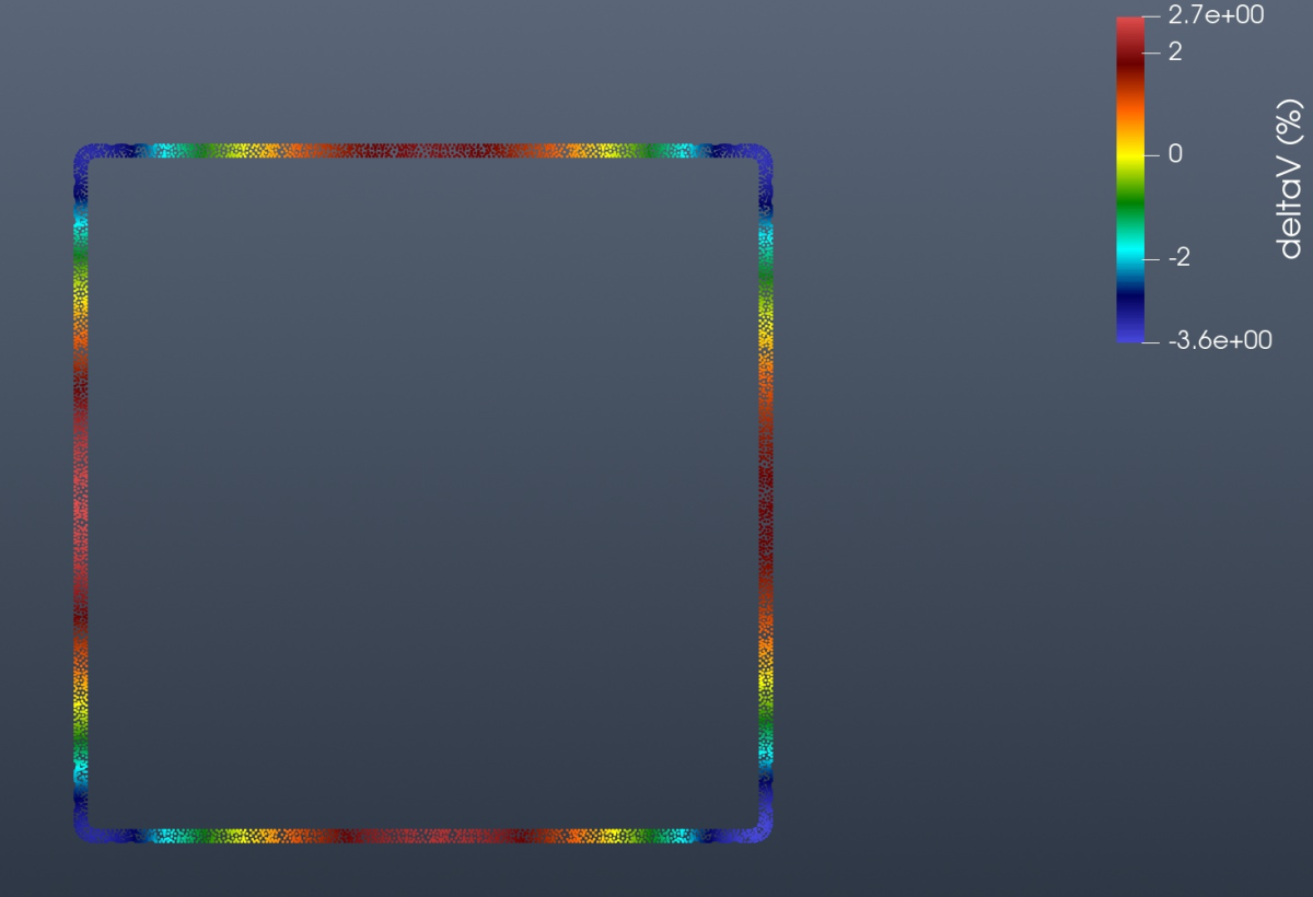
The map is worth reading slowly, because it shows what a bearing plan actually does. Mean exit velocity is 54 mm/s. Point by point the residual runs from 3.6 per cent slow at the corners to 2.7 per cent fast at the middle of each wall, which is the familiar signature of a box section: a corner sees more die contact per unit of metal than the middle of a wall does. Averaged over the eight zones the perimeter was divided into, the spread is 0.8 per cent. That is the number the bearing lengths were tuned to.
At the press it was a single trial. The first billet produced a good profile, the die went into production without a correction, and what came off the press matched what had been on the screen.
The die was not unusually simple and the shop was not lucky. The correction still happened. It happened on the screen.
A bearing plan is a hypothesis about how the metal will move. A flow simulation is where you test it, and a typical run completes in about 30 to 40 minutes, which is short enough to compare two or three bearing variants inside the same working day. Four things are worth looking at every time:
None of these replace the die maker's judgement. What they change is where the judgement is applied. A correction found in simulation costs half a day of somebody's attention. The same correction found at the press costs a trial, a strip down, a re nitriding cycle and a slot in next week's schedule, and it costs it again if the second trial is wrong too.
Bearing length is the parameter that decides whether a profile comes out straight. The information needed to set it usually exists on the 2D drawing already; the cost is in carrying it into 3D and in testing it. Do both before the die is cut and the press stops being the place where you find out.
Upload a die drawing and we will model it, set the bearings from your own drawing and show you the velocity field on your section, not on a demo part.
