Fancy Box
Exclusively for Extrusion Die Makers
Integrated Full Software Solution
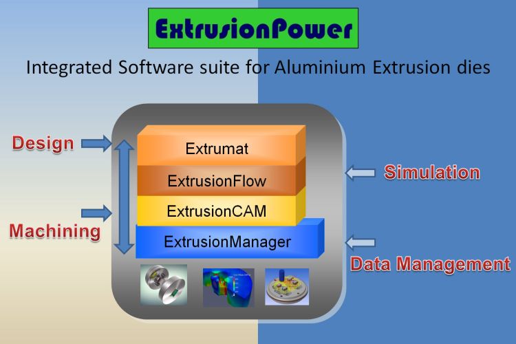
With ExtrusionPower, all production technologies—CAD, CAM, and Simulation—are integrated into a single platform. The modular structure of the different disciplines allows for the use of any required technology, such as CAD, CAM, or Simulation. All data is managed in a single database.
It is crucial that all processes in aluminum extrusion die production—from 2D design to 3D design, as well as CAM and simulation—are seamlessly interconnected and managed within a single shared database. ExtrusionPower is the industry’s unique solution that provides all these technologies in a single software package.
- Automate processes to reduce lead times
- Use integrated validation tools throughout the process
- Eliminate unnecessary and costly steps
ExtrusionPower is one of the world’s leading 3D CAD software solutions used in aluminum extrusion die design. In addition to specialized aluminum extrusion design functions, it streamlines and accelerates the entire extrusion process through its Manufacturing (CAM), Simulation (FEA), and Product Data Management (PDM) modules.
ExtrusionPower increases efficiency and delivers significant time savings in die production.
Aluminum die design is generally tied to the die designer’s experience. While this experience may sometimes take the form of in-house design rules and standards, it is typically stored in the designer’s mind, making it difficult to transfer this knowledge to others.
In die-making, the “trial and error” method is also frequently used; newly prepared dies are produced solely for testing before the final shape is given. In many cases, however, reproducing dies that have reached the end of their service life—especially if the die was produced using traditional manual methods—poses a problem.
3D extrusion die models stand out in today’s competitive environment due to their high quality and suitability for rapid production.
ExtrusionPower standardizes companies’ design and production methods, transferring mold designers’ knowledge into a 3D CAD environment.
ExtrusionPower standardizes companies' design and production methods, transferring die designers' knowledge into a 3D CAD environment.
Applications
- Solid Dies and Hollow Dies
- Port Hole Balance (ExtrusionFlow)
- Welding Chamber Design (ExtrusionFlow)
- Mandrel Design Wizard
- Parametric Design of Hollow, Bearings, and Other Die Set Components
- Automatic Modeling of Bearing Lengths
- Weight Optimization of Profiles
- Design of Cooling Channels
- Adjustment of Back Taper at Die Exit
- Bridge Design Wizard
- Support for DXF/DWG, IGES, STEP, Creo, and Other Formats
- Integration with PDM and ERP Management Systems
- Automatic Generation of 2D Drawings from 3D Models
- Technology Advisor” for Extrusion Die Design
- “Die Configurator” Feature for Customer Data Management
- Fully Automatic Die Set Design (Extrumat)
- Automatic CNC Machining (3–5 Axis) (ExtrusionCAM)
- Stress, Deformation, Temperature, and Flow Simulation (ExtrusionFlow)
Frequently Asked Questions
ExtrusionPower is a comprehensive CAD/CAE/PDM software suite developed to accelerate the design and manufacturing of aluminum extrusion dies.
ExtrusionPower Drafting : A 2D CAD software solution.
Extrumat : A module that automatically generates 3D models from pre-designed 2D drawings.
ExtrusionFlow : A 3D extrusion simulation solution that provides real-time feedback to the designer by calculating stress, deformation, temperature, and material flow during the design phase.
Bearing lengths on the mandrel and die plate are critical factors affecting aluminum flow within the die set. In standard CAD systems, modeling these bearing lengths is time-consuming. In ExtrusionPower, bearing length values are extracted from 2D drawings and automatically applied to the 3D die model. Bearing lengths on the mandrel and die plate are critical factors affecting aluminum flow within the die set. In standard CAD systems, modeling these bearing lengths is time-consuming. In ExtrusionPower, bearing length values are extracted from 2D drawings and automatically applied to the 3D die model.
Die Set Configurator This feature, specifically designed for extrusion die manufacturers, enables the rapid utilization of customer-specific technical die data, such as die set dimensions, outer profiles, pin and bolt connection parameters, and even customer-specific drawing dimensioning templates. When a designer selects a customer, all relevant data is automatically loaded into ExtrusionPower.
ExtrusionManager: A PDM (Product Data Management) solution that organizes die designs and related files within a secure database, enabling users to easily manage drawing revisions, control access rights, and handle file upload and storage.
Extrumat : A module that automatically generates 3D models from pre-designed 2D drawings.
ExtrusionFlow : A 3D extrusion simulation solution that provides real-time feedback to the designer by calculating stress, deformation, temperature, and material flow during the design phase.
Bearing lengths on the mandrel and die plate are critical factors affecting aluminum flow within the die set. In standard CAD systems, modeling these bearing lengths is time-consuming. In ExtrusionPower, bearing length values are extracted from 2D drawings and automatically applied to the 3D die model. Bearing lengths on the mandrel and die plate are critical factors affecting aluminum flow within the die set. In standard CAD systems, modeling these bearing lengths is time-consuming. In ExtrusionPower, bearing length values are extracted from 2D drawings and automatically applied to the 3D die model.
Die Set Configurator This feature, specifically designed for extrusion die manufacturers, enables the rapid utilization of customer-specific technical die data, such as die set dimensions, outer profiles, pin and bolt connection parameters, and even customer-specific drawing dimensioning templates. When a designer selects a customer, all relevant data is automatically loaded into ExtrusionPower.
ExtrusionManager: A PDM (Product Data Management) solution that organizes die designs and related files within a secure database, enabling users to easily manage drawing revisions, control access rights, and handle file upload and storage.
You can machine all components of a die fully designed in 3D on a CNC machine. The goal is to achieve 100% machining on the CNC.
If all die components are drawn on separate layers, you can generate the complete 3D model within 3 minutes using Extrumat.
Solid dies, hollow (porthole) dies, zero bearing, and butterfly die types are supported.
By specifying bearing transitions and heights in the 2D technical drawing, you can automatically generate them within the 3D software.
It automatically transfers text and slots, key slots, die sets, pins and holes, bolts and holes, and threads defined in 2D into 3D. You can also create them later directly on the 3D model if preferred.
You can automatically generate a 2D technical drawing from the completed 3D model. If you have previously defined a template, the 2D drawing will update itself automatically whenever the 3D model changes.
With ExtrusionFlow, you can create the billet and define the required parameters within the same environment — without leaving ExtrusionPower — and launch the simulation in just a few minutes.
Additionally, the calculation time is shorter compared to other simulation software.
With ExtrusionManager, you can register 3D models, 2D technical drawings, and all associated documents into a database, enabling effective search, revision tracking, bill of materials (BOM) generation, user authorization, and full lifecycle management of all your data.